- Home
- Registration
- Site Tools
- Articles
- Swap n Shop
- Contesting
- Grounding information for everyone
- History of the Central Alberta Amateur Radio Club
- CAARC owned Repeaters
- Club Repeater Info
- GMT Time Conversion Table
- VE/VA6 Incoming QSL Bureau
- Pine Lake Tornado Friday July 14, 2000.
- Amateur Radio to the Rescue
- CANWARN
- HAM Nation with Bob Heil K9EID
- Net info
- Events.
- ARES
- Links and On line study course.
- Field Day 2019
- Members D/L
- Forum/Swap and Shop
VE6BLD
Welcome to the CAARC web site. I have been a Ham since 1978 and I am active on most modes from HF to UHF Satellite communications.
Posts by VE6BLD

CAARC Members receive awards for volunteering during the last year.
Dec 20th
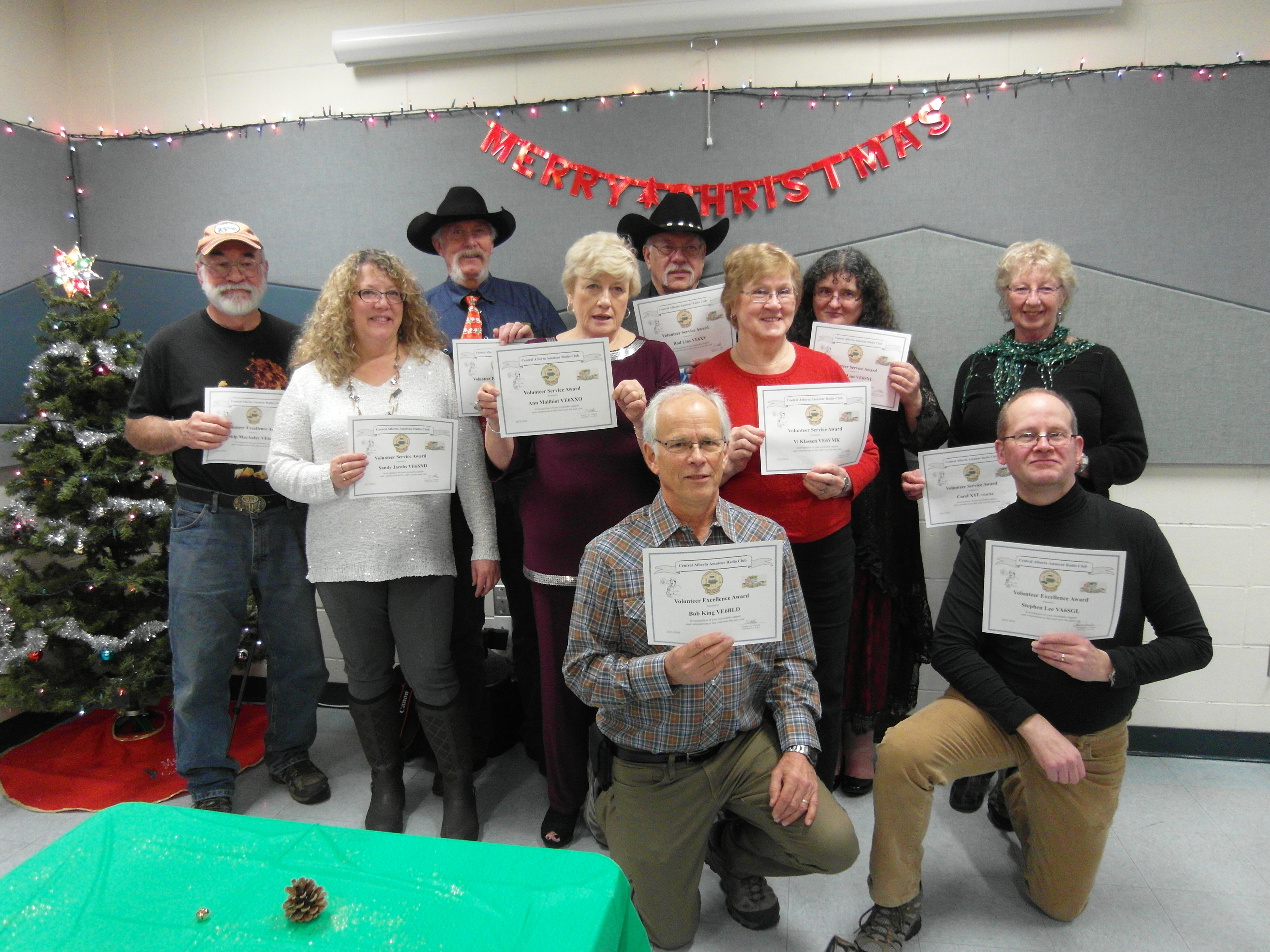
CAARC Members receive awards for volunteering during the last year. Congratulations to the members who received Volunteer Service and Volunteer Service with Excellence awards.
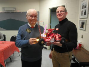
Congratulations to Doug VE6DJC on winning the GIZMO! We look forward to seeing what he adds to it for next year’s Christmas dinner!
Gallery Editing Unavailable while being repaired
Nov 2nd
The Gallery is experiencing a PHP problem after our hosting company updated their PHP CMS software. Â (Nov 7 th) You can now view the Gallery by clicking the Gallery drop down menu but you cannot add or edit anything in your gallery. We are trying to resolve the problem.
Bob
Webmaster
CAARC
Amateur Tower Protocols
Sep 26th
A good one for the web. Its for Calgary but the laws are federal.
Rick
VE6RAK
This message for our members in Calgary, Forwarded from Wally:
Hello all,
I was asked to help find some info on what exactly the rules for towers were within the City of Calgary. I finally tracked down the brochure from the City regarding towers and it is attached.
Bottom line is they do not have direct authority over towers but encourage some protocols be observed (kind of a good neighbour policy). There is a City phone number to call if needed as well.
Basically, towers that do not exceed 15m, and with associated antennas that do not exceed 18.75m, do not require any consultation but Amateurs are encouraged to follow the notification guidelines in the document.
There may be restrictive caveats in some neighbourhoods though, and those should be listed in the property documents.
This would be a great document to have available to all hams via their respective club websites. If anyone sees that there are other clubs that are not represented in this email please forward a copy to them or send me their contact info and I can pass it along.
Thanks,
Dave VE6GAD
73 de VE6LK/AI7LK
..Vince
city-of-calgary-protocols-concerning-amateur-towers-1
New volunteer net control operator
Apr 19th
We have a new volunteer for the Monday evening net controller.
Thanks to Maria VA6TFL for your willingness to help with the net.
Any other volunteers would be welcomed to add to the list.
Thanks to the five other net controllers for taking your turn.
Please check Updated Net Controller List under the Net info TAB
73
Bob VE6BLD
CAARC Net Controller Co-ordinator
Canwarn Training
Mar 24th
CANWARN, acronym for CANadian Weather Amateur Radio Network
Please note that CANWARN is not about storm chasing, it is about putting trained eyes at the local level to confirm what is happening under severe weather and communicating that information to the Meteorological Service of Canada.Here’s how CANWARN works in Central Alberta. When the regional weather forecast office (for the prairies this is the Prairie Storm Prediction Centre in Winnipeg, MB) would like to get ground observations of potentially severe thunderstorms they telephone the CANWARN person whom they have listed as the call-out person for the area of interest. In Central Alberta this will be the same people that are listed as ARES emergency coordinators. All Central Alberta and Olds ARES EC’s are trained CANWARN network controllers. The mechanics of how the net operates, local hams are notified and how their weather reports are forwarded to the forecast office are up to the CANWARN net controller. CANWARN Net Control may relay the observations or may elect to use a phone  to put the forecasters and amateur observer in direct contact.Typically, the person contacted by the Meteorological Service of Canada notifies the affected-area CANWARN hams who then radio their weather reports to their CANWARN Net Control Net. Net control then forwards the weather observations to the weather forecast office on a dedicated 1-800 phone number. As the storm moves along, reports would hopefully still come in from either stationary or mobile spotters allowing weather forecasters to continually compare the Carvel and Strathmore Doppler radar to what is being observed at ground level (below the radar horizon) and adjust their weather forecasts, Watches and Warnings accordingly.

New CAARC Executive for 2015 – 2016
Nov 24th
The Annual General Meeting was held on Wednesday Nov 18th at the Red Deer Search and Rescue. Congratulations to the members who were elected to the new executive.
CAARC Executive for 2015 – 2016
Past President   Bob King VE6BLD
President– Stephen Lee VA6SGL
Vice President– Rod Lins VE6XY
Secretary-Â Sandy Jacobs VE6SND
Treasurer– Karen McKinney VA6LDY
Directors
- Brian Davies VE6CKC
- Garry Jacobs VE6CIA
- Greg McKinney VA6GMC
- Jeff Low VA6JL
- Mike Mailiot VE6MIM
 Appointments
Repeaters
Skip MacAulay VE6BGT
Emergency Coordinator
Jeff Low VA6JL
Publicity
Bob King VE6BLD
Webmaster
Bob King VE6BLD
Net Control
Bob King VE6BLD

45th Anniversary a Success
Jul 17th
The 45th Anniversary Red Deer Picnic and Hamfest was a huge success. There were 112 people registered.  On Saturday morning Radio World and other flea market vendors enjoyed selling new and used radios and accessories under a beautiful and sunny sky. Greg and Karen and Karen’s parents began the process of roasting of the pig at 3:00 AM! Thanks for your generous donation of the pig and all your time!  Everyone enjoyed the roasted pork and the pot luck dinner Saturday evening.  Following the meal we watched the 45th anniversary video produced by Vance VA6VAN. Thank you Vance, for editing the pictures and videos sent from numerous hams. The weather was great Sunday morning for the pancake breakfast, egg toss and the  draw prizes.
There were many people who helped in various ways to make our 45th anniversary hamfest and picnic a resounding success. A special thank you to Phyllis and the ladies from the 160 gang from Camrose for organizing the fun craft again this year! Â Thank you everyone!
Bob King VE6BLD
CAARC President
Click pictures to see larger files

Pixie II v5.1 40 m QRP xcvr Kit by Earl 4Z4TJ
Jul 12th
Pixie II v5.1 40 m QRP xcvr Kit
This small kit is a version of the old Pixie II, two transistor, direct-conversion CW “transceiverâ€. Many Pixie IIs were made using Manhattan or dead bug technique. Now a Chinese PCB version is available   on line at such a low price that you will say:
“how can I not build this and try it on the airâ€.
In this application note I will share some of my experiences and suggestions regarding the kit. The first question that occurred to me was: “Is such a simple circuit effective as a communications device?â€Â The answer is yes, but with severe limitations. In any event it is a fun project well worth the money.
The circuit is simple and mostly self-explanatory. It incorporates some of the later mods developed for the Pixie II. Q1 is a Colpitts crystal oscillator using a reverse biased silicon rectifier as a varicap to pull the crystal frequency the 700 -800 Hz required to give a signal a pleasant tone when in receive mode. This function also gives a small range RIT to clarify signals when listening. The frequency offset is adjusted with W1, the 47K potentiometer.
In transmit Q2 functions as a simple PA with a pi LPF output. This stage buffers the oscillator and increases power to several hundred mW. I measured 250 mW with a 9V supply, 500mW with a 12V supply (see photos). General purpose 2N2222 type transistors are frequently used in Pixie II circuits. I looked up the transistors supplied with the kit and was pleasantly surprised to find the kit manufacturers have gone to the effort of selecting components specific for local oscillator and power amplifier functions.
In receive, Q2 functions as the product detector in a direct conversion receiver with Q1 as the LO and U1 amplifying the detected audio to provide earphone volume. LSB as well as CW signals may be received.
Start construction by inserting 6-32 x ¾†hardware in each of the corner holes. Head of the screw goes on the bottom (solder) side of the PCB. Finger tighten.   These screws act as legs that allow the PCB to rest flat when soldering components. If you plan to mount the PCB in a case this is the time to mark the mounting holes.
Solder the potentiometer and the socket for U1. If you also wish to use this pot as a RIT use wires and a 47 K potentiometer mounted on the “front panelâ€. Next solder the resistors, capacitors (polarity) and diodes (polarity) and inductors in that order. Solder the transistors. Solder the 3 mm stereo sockets the BNC antenna socket and the power socket. I measured all the disc capacitors in the kit and found that they are 20%. The inductors are also 20%. I added a ferrite bead on the lead of L1 to bring the inductance up to the nominal value. L2 was within 10% so I used it. I was not happy about using -20% value capacitors in the LPF so I purchased 1% ceramic capacitors at the local components shop for 15 cents each. It took about two minutes to wind a new 1 mH L2 inductor (15 t) on a T30-2 powdered iron (red) toroid. With the L/C meter attached I spread the windings till the exact value was found. Fix the windings in place with a drop of glue.
Solder the 7.023 MHz crystal (you may wish to look in your junk box for a crystal that will put you on a QRP calling frequency; 7.030 in EU and 7.040 in North America).
Measure resistance across the power input. Connect the 50 ohm 1 W composition resistor supplied with the kit or other dummy load to the antenna socket.  With a mA meter in series apply 9 – 12 V. Current should be approximately 15 mA. If it is much higher than 15 disconnect power immediately and check your work. (D1 provides reverse polarity protection so a 500 mA fuse might be in order.)  Insert a Morse key in J3. Listen for the oscillator on your station transceiver or connect scope probes across the antenna dummy load 51 ohm 1 W resistor supplied with the kit.Â
If the oscillator and PA are working as expected insert U1, connect headphones and a 40m antenna. A 9V – 12 V battery works.
Phone another ham in your city and get him to zero beat your signal and then transmit. Adjust the 47K trim pot for a pleasant tone. You are on the air!
In the evening I connected a 9V battery, Air Canada complementary earphones and my 40m delta loop antenna.   CW stations from EU could be heard and tuned with potentiometer W1.
Now, where did I put that straight key that I used 40 years ago?
CW chirp issues were solved by: 1) Preventing a change in voltage across the varicap, D2, when keying by keeping potentiometer W1 in the middle of its range. 2) Addition of a 22 uF 25V SMT chip capacitor on the bottom of the PCB, across the terminals of the power input socket. To solder one side of the capacitor I scraped away some of the solder mask on the PCB — the other end went tight against the +ve lug of the power socket. (Check for shorts before applying power.)
RF power output with a 12 V supply was found to be 500 mW, as shown at left. In addition, the higher supply voltage yields a waveform appearing closer to a clean sine wave, (photos above) generating fewer harmonics.
Note: LPF: I checked for 2nd and 3rd harmonics and they are easy to find within the shack. I believe that higher quality components in the LPF will reduce harmonic radiation. However, another ham in the same city could not hear the second harmonic (this is my spectrum analyzer equivalent test).  So, even with sub-optimum suppression, the second harmonic will be at a level of approximately 0 dbm – not a level that will wreak QRM havoc on 20m and 15m CW (second and third harmonics).
On the air results.
Hams within a 200 Km radius could hear the QRP CW signal. After correcting the chirp issue reports were good. Surprisingly the direct conversion receiver also let me hear them easily, so 2 way QSOs are definitely possible. Listening on 40m just after dark let me hear most of the 40m CW band – all at once. Stations could be peaked by adjusting the 47K trim pot. Where a few individual CW signals could be identified I found them on my FT-450 – surprisingly they were not S9+ signals but pretty ordinary S7 signals, indicating that the direct conversion receiver is quite sensitive. Good sensitivity combined with poor selectivity effectively restricts 2-way communications use to daylight hours. In spite of the receive limitation, it is pretty amazing that two way communications are possible with such simple, low cost equipment.
Conclusion
Lots of fun for the money!
To download this original article click this link