va6tj

This user hasn't shared any biographical information


Posts by va6tj

Xmas DX Contest

New Award and Operation Alert                    

The Israel Amateur Radio Club (I.A.R.C) is proud to announce a new national award program entitled:   Holyland Christianity On The Air (HOCOTA).

This program will include amateur radio operations from numerous sites of major Christian significance. The sites were selected based on well documented research and archeological history as documented in the Holy Bible and other Christian works.  We believe that the connection of operating from these holy sites will not only appeal to Christian amateur radio operators but to amateurs of all faiths and beliefs.

The program accreditation will be built from ‘blocks’ of sub-awards derived from specific geographic locations. Activities will run throughout the year with special operations mainly during Christmas and Easter.

The HOCOTA Program will commence during Christmas 2016 (23-25 December) by Four special event multi operator stations. The current sub-program is called the ‘Jesus Miracles Award’.  Within this block of the HOCOTA Program we’ll start with some of the most significant miracles that Jesus Christ performed around the Sea of Galilee.

Therefore, the Christmas 2016 operation shall include:

  1. 4X9XMAS-Tabagha- https://en.wikipedia.org/wiki/Tabgha
  2. 4X7XMAS- Kursi- https://en.wikipedia.org/wiki/Kursi,_Golan_Heights
  3. 4X3XMAS-Mount of Beatitudes – https://en.wikipedia.org/wiki/Mount_of_Beatitudes
  4. 4X2XMAS- Yardenit- https://en.wikipedia.org/wiki/Yardenit

QSL information as well as program rules will be published separately.

Awards – Our goal is to enable automatic award opportunities and we are also considering the availability of an impressive, unique plaque.

4Z4DX                                                           4Z1RZ

Dov Gavish                                                 Zurial Rienstien

IARC Special Events Manager                             IARC President

After the rain

SAM_3171

Mushroom at VA6TJ


mushrooms


At VE6EGN


20160717_204154

At VE6HPY


To have your Fungal Photo posted email it to VE6BLD


Ham Radio – when all else fails

rural internet

Another QRP CW Kit

Super Rock Mite 40m CW QRP XCVR

schematic finished board


I bought this kit for US$16 including postage.  It features a keyer and substantial output power (see below).  I am posting some of the documentation inconsistencies that I found – hopefully this will smooth the build for others.  I bought my kit here   http://www.banggood.com/DIY-51-Super-Rock-Mite-RM-Kit-CW-Transceiver-Shortwave-Telegraph-p-991246.html

caveat emptor


Clarification to Bill of Materials (list of components)

  • C22 to C34 0.1 uF (104) disc capacitors. Approximately half of these capacitors tested within 20% of designated value, the rest within 50% of designated value. One capacitor was 0.028 uF.  All these capacitors were replaced with quality ceramic components testing within 10% or better of designated value.
  • C25 and C26: these are apparently the same capacitor. Documentation inconsistency between versions?
  • C13 to C21: 0.01 uF (103) disc capacitors. Less than half were within 20% so I replaced them all with good ceramic capacitors.
  • C35: 470 pF is necessary to prevent oscillation in the NE5532. Put it in.
  • Install the 100 pF capacitor located on the edge of the board between W2 and U3.
  • Y1, Y2, Y3: I used DIP header pins on the board and soldered the crystals to DIP sockets. Cut strips of 3 pins each and remove the center pin for the header on the board.  This arrangement will permit you to QSY to 7.030 / 7.040 when you find some appropriate crystals.  I found 7.0375 crystals in the same holder at US$0.10 each from Tayda Electronics and they should arrive in the mail any day now.  The pins will also let you painlessly try the VFO/DDS mod as per the March 2016 QST article pp 39-44.

board with caps and resistors

  • R2, R3: The schematic states that 1 W resistors should be used however 1/4W resistors are supplied. R3 is in series with the emitter lead of the 8050 driver transistor. I looked up the specs on this transistor and it can handle sufficient current to fry a ¼ W resistor. I didn’t have a 1 W 22 ohm resistor in my parts so I used a 2W resistor.  It protrudes a bit but fits. DO NOT use a wire wound resistor for R3 .  I check inductance of the resistor before using it.  For R2 I found a 1/2W 22 ohm resistor to substitute but I am not convinced it is necessary.
  • Electrolytic capacitors: The BoM shows 16V electrolytics.  My kit supplied 25V capacitors.  I strongly recommend that you do not use 16V units with a 12V (13.6V) supply.
  • D3: I have used the 1N4001 as a varicap however I also once wasted several hours troubleshooting because a 1N4001 diode somehow prevented crystal oscillation. I found that a BB221 varicap works well so that is what I used.
  • L1 and L2: My toroid calculator gives a value of 1 uH for 16 turns on a T37-2 form. The photo in the Engrish instructions shows 17 turns.  The LPF is not working well for me as I am seeing a drop of about 12 V P-P between the input and output sides of the filter section.  I used tested capacitors, within 2% of given value,  in the filter.  If anyone knows how to calculate the optimum values for L1, L2 please send me an email (QRZ.com). 


output filter with measurements

  • Q2 output transistor. I cut a mica power transistor insulator to fit under the heat sink and superglued it in place. The solder resist under the heat sink is a good insulator but …


final transistor insulator


  • LEDs: the long lead goes into the square pad. I used the green LED for receive and the red LED for transmit.
  • For the initial smoke test, after connecting a dummy load to the antenna terminals, I put a 10 ohm 5W resistor in series with the supply.  Current draw through the 10 ohm resistor was 85 mA.
  • I am getting 1.1 watts out into a calibrated watt meter using a 12 V battery as a supply. As mentioned above, there is definitely a problem with my LPF.  Once I get the LPF issue sorted out and up the supply voltage from my 13.6V buss, I expect to see several watts RMS out.
  • I used a USB to RS232 cable to connect the Rock Mite to my computer after finding the English version of the software. The software definitely does something but needs further research.  Who designs a board with an RS232 interface in 2016?  I was lucky my patch cable worked.


On the air:  I received reports of clean keying from several hams within 100Km.  A CQ in the evening brought a prompt response from Europe.  The QSK works fine.  My straight key was recognized after sending a few V’s.   The side tone leaves room for improvement.  I connected the audio out through a small digital audio amplifier module. I am confident that a good CW operator could fill his logbook using this transceiver.  For the rest of us I suggest working stations within a few hundred Km during daylight hours – the large number of stations heard concurrently after dark overwhelm my ability to sort out signals by tone.

The PCB layout shows some thought and some nice features.  It was designed without mounting holes made to slide into a ready-made case.  As may be seen on the photos I had a groove machined into some aluminum bar stock to hold the PCB.

This kit fails its “ISO9002 audit” because of the “instructions” and the poor quality of the disc capacitors supplied.  Google does a terrible job translating Mandarin to English.


Is your coax genuine M17/74 or generic RG-213?

real and generic coax

An informative article on specifications for coaxial cable.  Download the article by clicking on the link below.

Transmission Lines ver 2

link to download instructions for the IRF 530 PA kit

Banggood IRF 530 PA Instructions V1.4


A newer version of the instructions incorporating corrections and suggestions from proof readers.  Thanks to K9HZ, KE7HR and ON7AN for their help with this project.  Any errors are mine.  Use at your own risk. Comments, corrections and suggestions most welcome.

Good luck with your build.


Earl, VA6TJ

HF PA amplifier kit: instructions decrypted from Chinese

DIY 45W SSB HF Linear Power Amplifier Amateur Radio Transceiver Shortwave Radio Development Board Kit

COMING SOON 

I just finished building this kit that I bought online (link above).  In my opinion it meets the main requirements of a kit for hams: 1) cheap 2) fun to build 3) it actually works.

So what’s the catch?  The instructions are either in Mandarin Chinese or in Google Translate English.  Amusing to read but difficult to follow.  So with lots of cogitation, head scratching, questions to several other hams, and the assistance of the boffins at Bletchley Park we are offering CAARC website readers a decrypted version of the kit instructions.

The first paragraphs are given below as a “teaser”.


These instructions are my attempt to put the “manual” supplied for download on the seller’s website into more conventional English.  They are based primarily on the “RF‐AMP‐2078 debug instructor V303”  (sic) downloaded from the website.  You will note that the schematic is dated 5 August, the BoM sometime in September and the PCB is marked “20151229”.  I found more than a dozen inconsistencies in values and markings between the PCB and the documents.  Also there appear to be several “typos” on the PCB silk screening.   I have endeavored to sort this out and update my documentation to match the PCB supplied with the kit.


It is no doubt feasible for an experienced builder to successfully assemble the kit using only the schematic and the silk screening on the PCB.  My objective is to make this inexpensive kit available to a wider audience of radio amateurs, who may feel less confident about building their first MOFET PA without some additional guidance.  Anyone who does not have previous experience soldering the small SMD parts used in this kit is advised to practice first. 


amplifier under test

A pdf file with the complete instructions will be linked to this post within the next few days.  Watch this space. 


Solar Powered projects

The objective of this project was to create an independent WSPR beacon transmitter.  As such it should operate completely independently – no computer in the shack, no internet time server and no power from the grid.


I found that a U3S kit + GPS kit both from QRP Labs met my requirements for a transmitter with internal controller, GPS disciplined frequency synthesizer and GPS timing.  WSPR operates on 2 minute time segments and timingGPS + U3S 
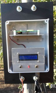
must be accurate to a very few seconds or no one will be able to decode your transmission.  Similarly the frequency band for WSPR signals is only a few hundred Hz wide, so if your frequency is not exact;  no reception.


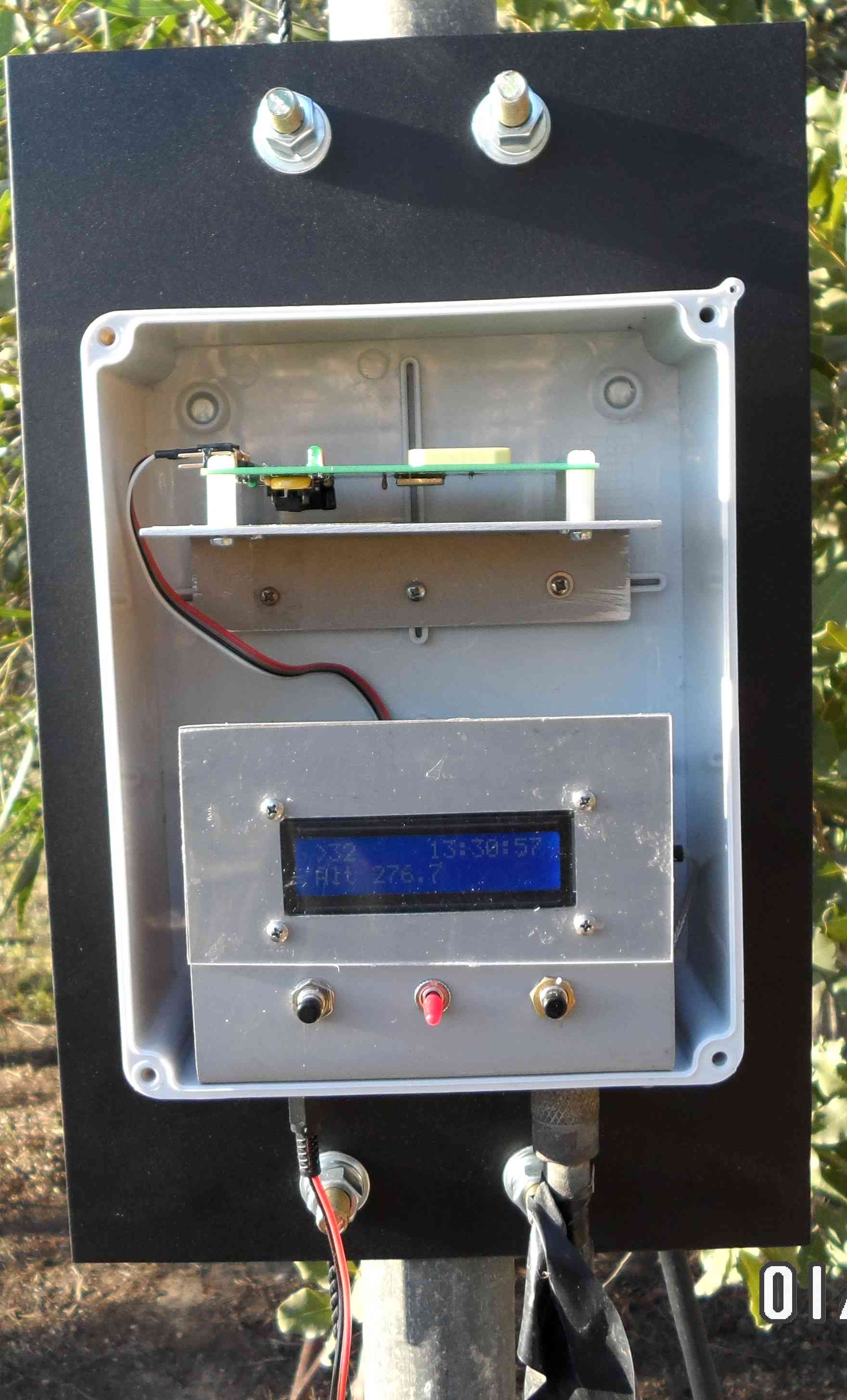
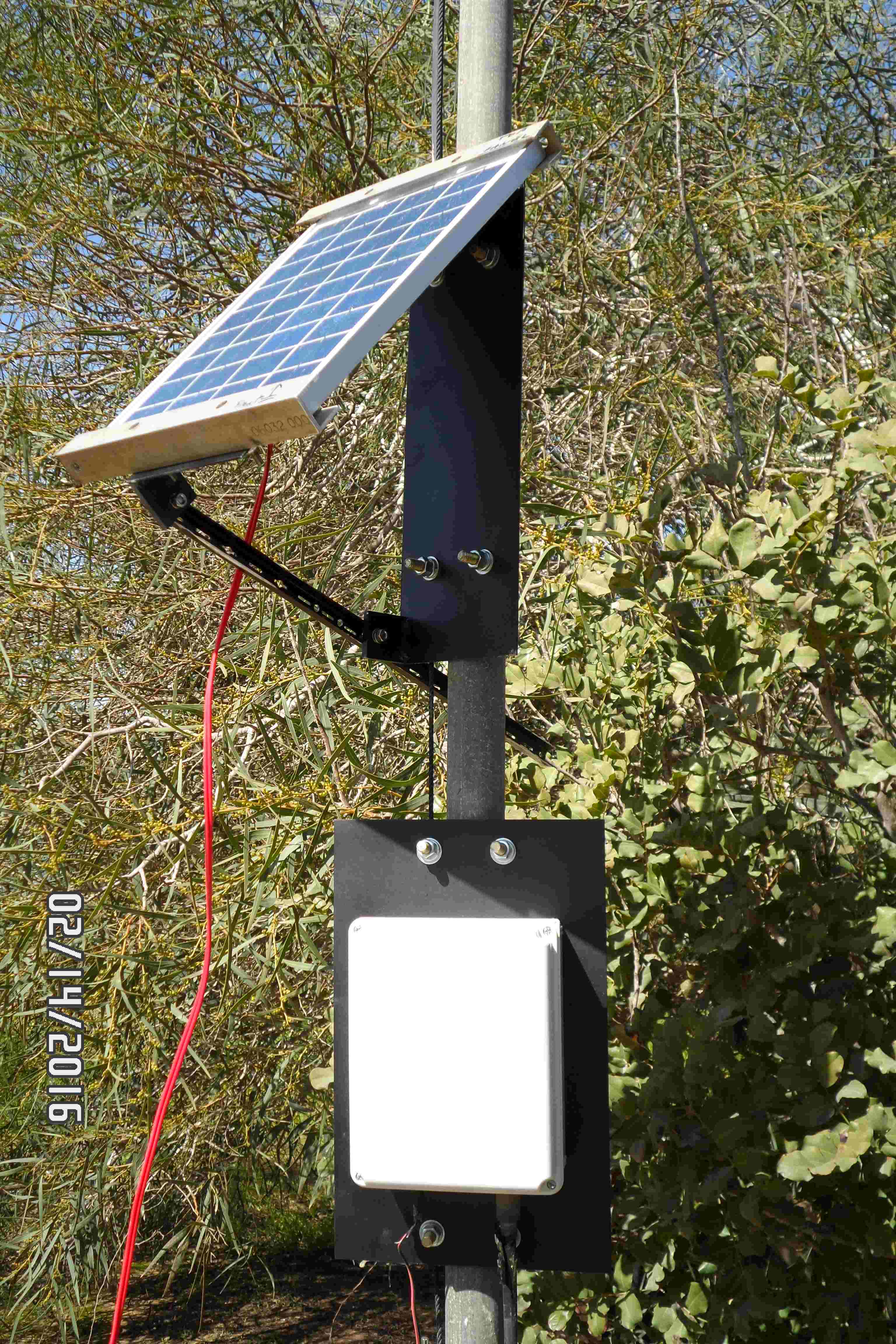
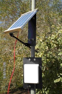
The photo at left shows the transmitter (bottom of the box) and GPS (top shelf) mounted in a weatherproof PVC electrical box.  The box is mounted on a steel plate, that allows the assembly to be attached to the 2″ pipe mast with U bolts.  (This transmitter puts out approximately 500 mW on 30m with a 25% duty cycle — 2 minutes on, 6 minutes off; the antenna is a dipole with the mast providing the center support.)

temporary panel installation


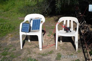
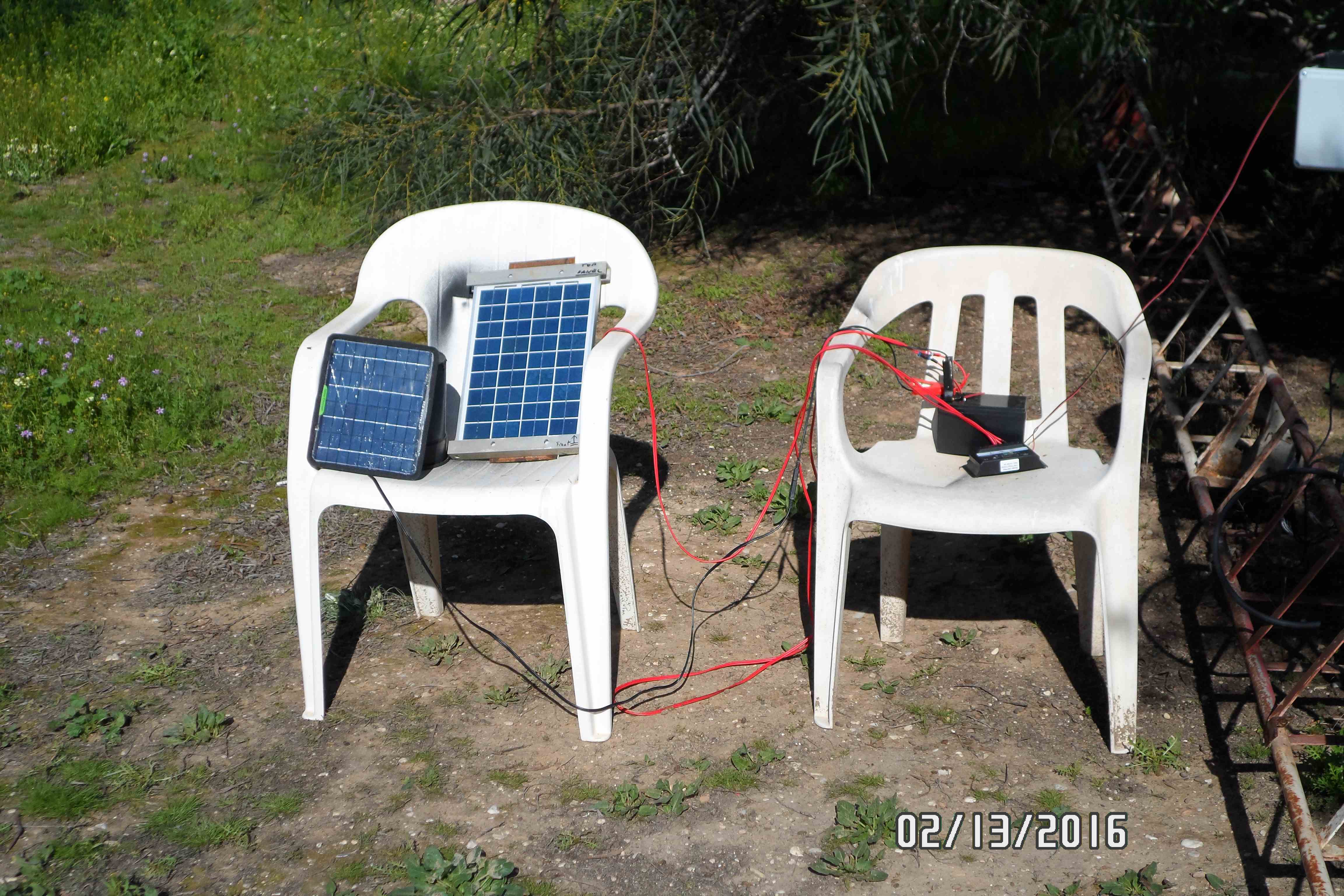
After getting the transmitter and GPS to work successfully inside the shack, I started my quest for independent power.  I started with a 5W solar panel and a 7 AH gel cell battery.  The 12V battery voltage is knocked down to 5 V for the transmitter using a low cost buck regulator module (internet shopping).  In the photo above, the smaller 5W solar panel is shown on the left hand chair next to the newer 10W panel that eventually came in the mail.  The charge regulator is on the right hand chair just in front of the battery.  This arrangement was almost good enough so I sprung for a larger, 12 AH battery.  The 10 W panel and the 12 AH battery easily carried the transmitter through the night until the morning sun could re-start the charge cycle.

mounting bracket clamped together

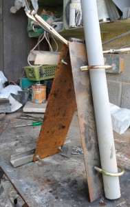
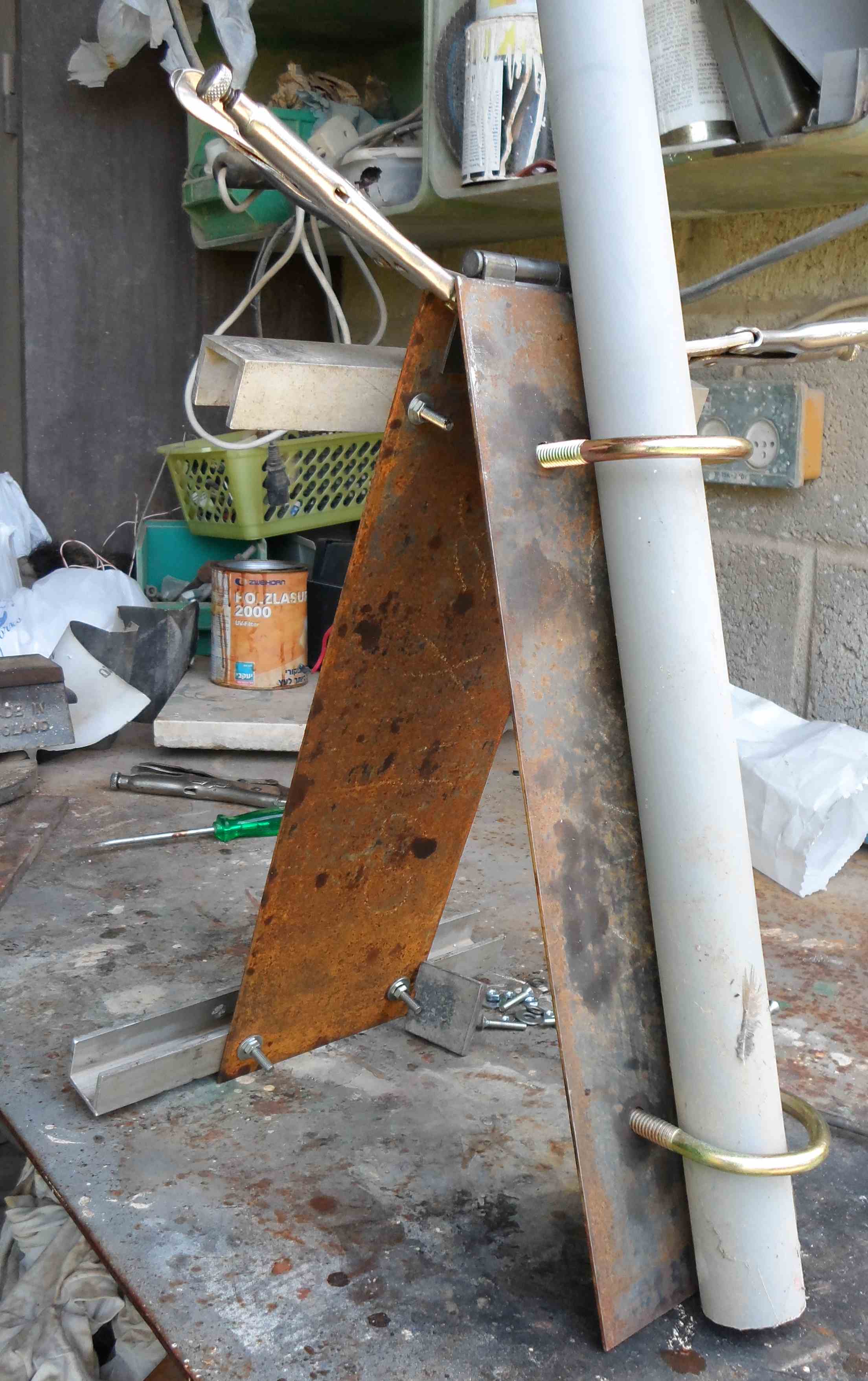
So it was time to fabricate a bracket that would hold the solar panel on the mast.  I wanted the bracket to be adjustable so I put a leaf hinge at the top.  The mounting holds the panel at an angle by moving the support arm from one hole to another.  A position for any season.

I used 2 mm mild steel plate for the bracket.  The solar panel is held in place by aluminum U channel that was left over from my main antenna tower project.  I believe that suitable aluminum profiles should be available from any aluminum window manufacturer.  I took considerable care positioning the plates and the hinge before welding it together.  After I cleaned up my welds and removed as much rust as possible from the plates I gave them a coat of galvanizing spray followed by blac
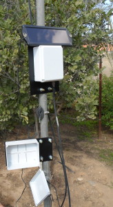
SAM_2401 croppedk enamel spray.

I originally intended putting the gel cell battery in the lower PVC box.  After I determined that I needed a larger capacity battery I used this box for the charge controller and the 5 V buck regulator.  The 1.8W Canadian Tire panel shown on the right was not used in the final system.

The 12 AH battery is sitting on the ground inside a plastic box from the Dollar Store and weighted down with a brick.  I will eventually get round to something more elegant, but it does work.

The whole system has been up and running 24/7 for some days now and appears stable.

You can see the WSPR beacons by going to http://wsprnet.org/drupal/wsprnet/map

Select the 30m map and a time period of 30 minutes. Click on any station call sign to see who is hearing who.


In summary I will list the components or modules I found suitable for making an independent power system:

  • Solar panel of sufficient power rating
  • Battery with sufficient storage capacity
  • Charge regulator
  • Regulator to drop the battery voltage down to that required by the circuits being powered (if necessary)solar panel with transmitter
  • Weatherproof boxes
  • Sturdy mounting system


Some possible applications:

  • repeaters
  • beacons
  • remote antenna tuners


Voltage Regulator Modules

regulator board


A whole range of small regulator boards or modules are available from your favorite on-line shopping sites for very little money.  I gave the most recently arrived unit a quick once over.

The on board voltmeter is fairly accurate but if you need to adjust voltage exactly I suggest a good multi-meter.

I measured quiescent current at 25 mA (compared to 5 mA with a 7805).

Voltage regulation was good; switching an 11 ohm load at 5 volts did not result in a noticeable drop.  The regulator IC stayed cold – at least until the load resistors started smoking.test setup

I put my scope across the load and found an interesting [Eastern Rockies] waveform about 0.5 V at 10 KHz.

output waveform

There is one 220 uF electrolytic across the output.  The scope suggests that some additional output filtering is in order.


All in all a useful piece of kit for only a very few dollars.

using “bargain” coax connectors

die on incorrectly threaded so239


I bought a package of 10 SO-239 chassis connectors on eBay at a great price.  The connectors looked good, teflon insulation, gold plated pins.  However it was not possible to thread a PL-259 male connector on more than 2 or 3 turns.

I then understood why the price was so low.  I decided that the solution was to re-thread the connectors.  I looked for a die at local tool stores but no luck –  I was told that 5/8-24 was a thread used in electrical connectors but not commonly used by machinists.  Checking on Amazon it became clear that the proper die was available at reasonable cost as a “gunsmiths” die.


As soon as it arrived I tried it.  I did not have a holder for this size die so I used a “Quick-clamp” with rubber pads.  I used lots of cutting oil and took my time cutting the threads.  The result was a bare brass thread which easily took the Amphenol PL-259 connector.

I don’t know if the manufacturer in China used a 16 mm die in place of 5/8″ or if they failed to take the thickness of the nickle plating into account when cutting threads.  Whatever the reason now I have the tool to make it right!


The photos tell the story.  73 and keep on building.  Earl VA6TJ


die on correct conn after rethreading rethreaded it worksu