Another QRP CW Kit
Super Rock Mite 40m CW QRP XCVR
I bought this kit for US$16 including postage.  It features a keyer and substantial output power (see below).  I am posting some of the documentation inconsistencies that I found – hopefully this will smooth the build for others.  I bought my kit here   http://www.banggood.com/DIY-51-Super-Rock-Mite-RM-Kit-CW-Transceiver-Shortwave-Telegraph-p-991246.html
caveat emptor
Clarification to Bill of Materials (list of components)
- C22 to C34 0.1 uF (104) disc capacitors. Approximately half of these capacitors tested within 20% of designated value, the rest within 50% of designated value. One capacitor was 0.028 uF. All these capacitors were replaced with quality ceramic components testing within 10% or better of designated value.
- C25 and C26: these are apparently the same capacitor. Documentation inconsistency between versions?
- C13 to C21: 0.01 uF (103) disc capacitors. Less than half were within 20% so I replaced them all with good ceramic capacitors.
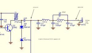
- C35: 470 pF is necessary to prevent oscillation in the NE5532. Put it in.
- Install the 100 pF capacitor located on the edge of the board between W2 and U3.
- Y1, Y2, Y3: I used DIP header pins on the board and soldered the crystals to DIP sockets. Cut strips of 3 pins each and remove the center pin for the header on the board. This arrangement will permit you to QSY to 7.030 / 7.040 when you find some appropriate crystals. I found 7.0375 crystals in the same holder at US$0.10 each from Tayda Electronics and they should arrive in the mail any day now. The pins will also let you painlessly try the VFO/DDS mod as per the March 2016 QST article pp 39-44.

- R2, R3: The schematic states that 1 W resistors should be used however 1/4W resistors are supplied. R3 is in series with the emitter lead of the 8050 driver transistor. I looked up the specs on this transistor and it can handle sufficient current to fry a ¼ W resistor. I didn’t have a 1 W 22 ohm resistor in my parts so I used a 2W resistor. It protrudes a bit but fits. DO NOT use a wire wound resistor for R3 . I check inductance of the resistor before using it. For R2 I found a 1/2W 22 ohm resistor to substitute but I am not convinced it is necessary.
- Electrolytic capacitors: The BoM shows 16V electrolytics. My kit supplied 25V capacitors. I strongly recommend that you do not use 16V units with a 12V (13.6V) supply.
- D3: I have used the 1N4001 as a varicap however I also once wasted several hours troubleshooting because a 1N4001 diode somehow prevented crystal oscillation. I found that a BB221 varicap works well so that is what I used.
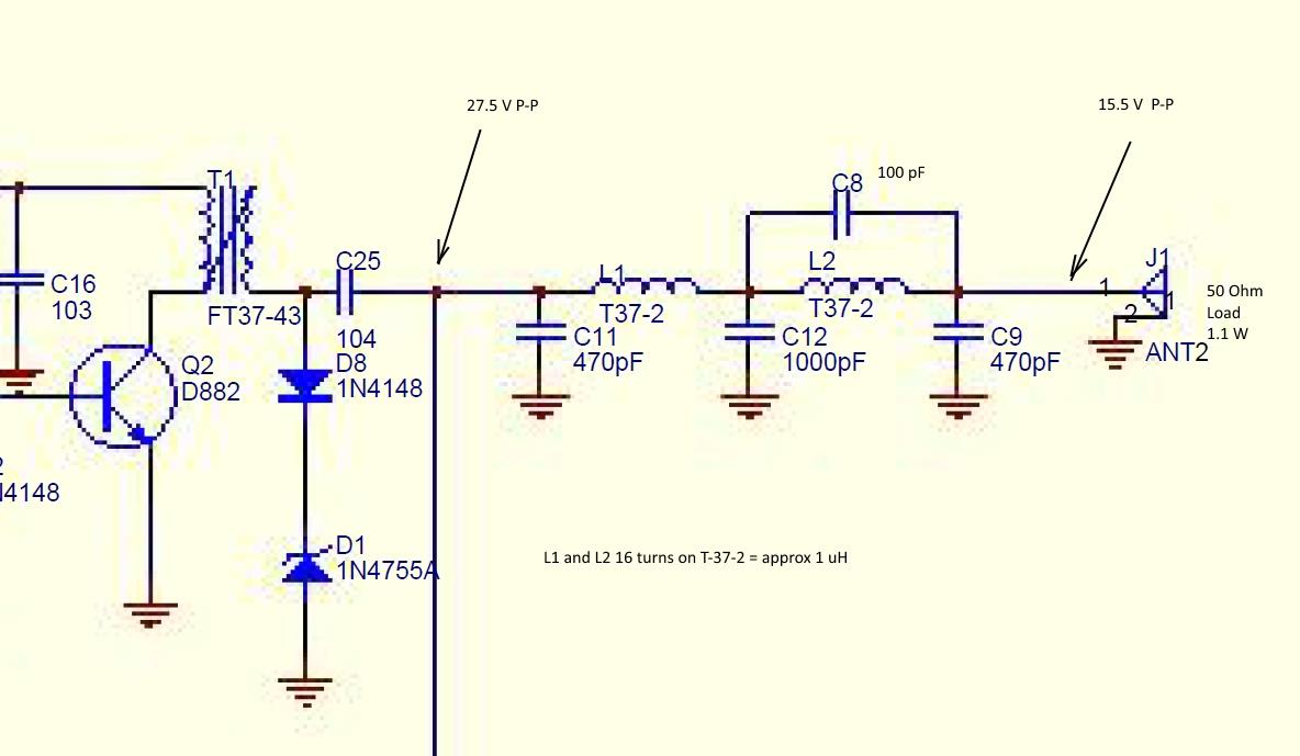
- L1 and L2: My toroid calculator gives a value of 1 uH for 16 turns on a T37-2 form. The photo in the Engrish instructions shows 17 turns. The LPF is not working well for me as I am seeing a drop of about 12 V P-P between the input and output sides of the filter section. I used tested capacitors, within 2% of given value,  in the filter. If anyone knows how to calculate the optimum values for L1, L2 please send me an email (QRZ.com).Â
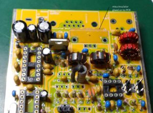
- Q2 output transistor. I cut a mica power transistor insulator to fit under the heat sink and superglued it in place. The solder resist under the heat sink is a good insulator but …
- LEDs: the long lead goes into the square pad. I used the green LED for receive and the red LED for transmit.
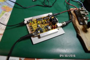
- For the initial smoke test, after connecting a dummy load to the antenna terminals, I put a 10 ohm 5W resistor in series with the supply. Current draw through the 10 ohm resistor was 85 mA.
- I am getting 1.1 watts out into a calibrated watt meter using a 12 V battery as a supply. As mentioned above, there is definitely a problem with my LPF. Once I get the LPF issue sorted out and up the supply voltage from my 13.6V buss, I expect to see several watts RMS out.
- I used a USB to RS232 cable to connect the Rock Mite to my computer after finding the English version of the software. The software definitely does something but needs further research. Who designs a board with an RS232 interface in 2016? I was lucky my patch cable worked.
On the air:  I received reports of clean keying from several hams within 100Km. A CQ in the evening brought a prompt response from Europe. The QSK works fine.  My straight key was recognized after sending a few V’s.  The side tone leaves room for improvement. I connected the audio out through a small digital audio amplifier module. I am confident that a good CW operator could fill his logbook using this transceiver. For the rest of us I suggest working stations within a few hundred Km during daylight hours – the large number of stations heard concurrently after dark overwhelm my ability to sort out signals by tone.
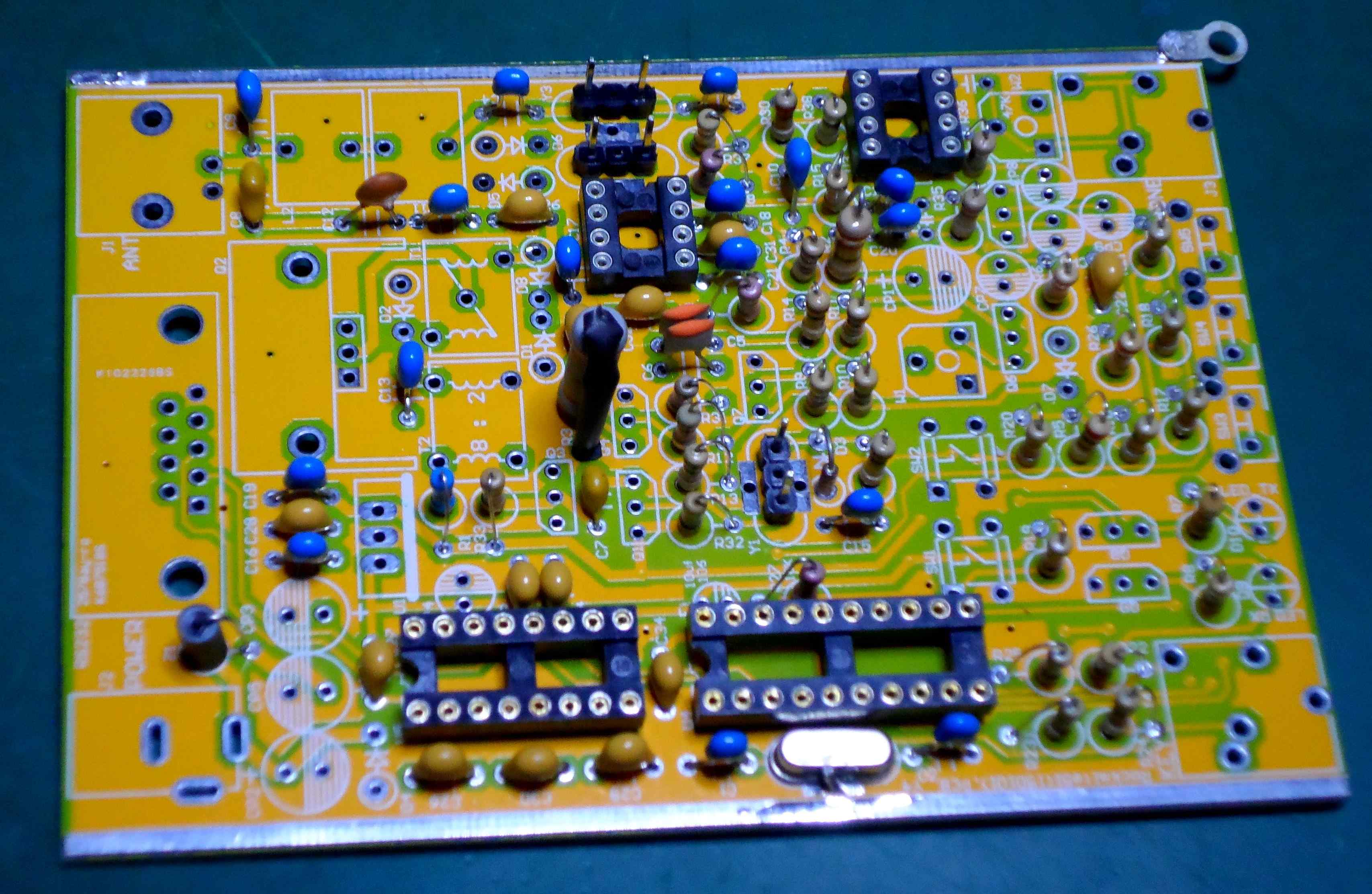
The PCB layout shows some thought and some nice features. It was designed without mounting holes made to slide into a ready-made case. As may be seen on the photos I had a groove machined into some aluminum bar stock to hold the PCB.
This kit fails its “ISO9002 audit” because of the “instructions†and the poor quality of the disc capacitors supplied. Google does a terrible job translating Mandarin to English.