New Award and Operation Alert                   Â
The Israel Amateur Radio Club (I.A.R.C) is proud to announce a new national award program entitled: Â Â Holyland Christianity On The Air (HOCOTA).
This program will include amateur radio operations from numerous sites of major Christian significance. The sites were selected based on well documented research and archeological history as documented in the Holy Bible and other Christian works. We believe that the connection of operating from these holy sites will not only appeal to Christian amateur radio operators but to amateurs of all faiths and beliefs.
The program accreditation will be built from ‘blocks’ of sub-awards derived from specific geographic locations. Activities will run throughout the year with special operations mainly during Christmas and Easter.
The HOCOTA Program will commence during Christmas 2016 (23-25 December) by Four special event multi operator stations. The current sub-program is called the ‘Jesus Miracles Award’.  Within this block of the HOCOTA Program we’ll start with some of the most significant miracles that Jesus Christ performed around the Sea of Galilee.
Therefore, the Christmas 2016 operation shall include:
- 4X9XMAS-Tabagha- https://en.wikipedia.org/wiki/Tabgha
- 4X7XMAS- Kursi- https://en.wikipedia.org/wiki/Kursi,_Golan_Heights
- 4X3XMAS-Mount of Beatitudes – https://en.wikipedia.org/wiki/Mount_of_Beatitudes
- 4X2XMAS- Yardenit- https://en.wikipedia.org/wiki/Yardenit
QSL information as well as program rules will be published separately.
Awards – Our goal is to enable automatic award opportunities and we are also considering the availability of an impressive, unique plaque.
4Z4DXÂ Â Â Â Â Â Â Â Â Â Â Â Â Â Â Â Â Â Â Â Â Â Â Â Â Â Â Â Â Â Â Â Â Â Â Â Â Â Â Â Â Â Â Â Â Â Â Â Â Â Â Â Â Â Â Â Â Â 4Z1RZ
Dov Gavish                                                Zurial Rienstien
IARC Special Events Manager                            IARC President
The Gallery is experiencing a PHP problem after our hosting company updated their PHP CMS software. Â (Nov 7 th) You can now view the Gallery by clicking the Gallery drop down menu but you cannot add or edit anything in your gallery. We are trying to resolve the problem.
Bob
Webmaster
CAARC
A good one for the web. Its for Calgary but the laws are federal.
Rick
VE6RAK
This message for our members in Calgary, Forwarded from Wally:
Hello all,
I was asked to help find some info on what exactly the rules for towers were within the City of Calgary. I finally tracked down the brochure from the City regarding towers and it is attached.
Bottom line is they do not have direct authority over towers but encourage some protocols be observed (kind of a good neighbour policy). There is a City phone number to call if needed as well.
Basically, towers that do not exceed 15m, and with associated antennas that do not exceed 18.75m, do not require any consultation but Amateurs are encouraged to follow the notification guidelines in the document.
There may be restrictive caveats in some neighbourhoods though, and those should be listed in the property documents.
This would be a great document to have available to all hams via their respective club websites. If anyone sees that there are other clubs that are not represented in this email please forward a copy to them or send me their contact info and I can pass it along.
Thanks,
Dave VE6GAD
73 de VE6LK/AI7LK
..Vince
city-of-calgary-protocols-concerning-amateur-towers-1

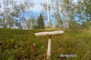
Mushroom at VA6TJ

At VE6EGN
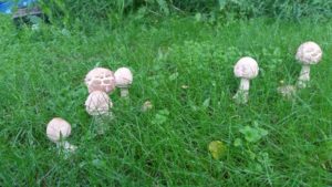
At VE6HPY
To have your Fungal Photo posted email it to VE6BLD
I won a couple of prizes at the 2016 CAARC picnic that were donated by Radio World. I will be in touch and thank them, but I see they have a page on their web site full of appreciation from various organizations. I think it would be appropriate for someone from the executive or the organizing committee to write an email of thanks. Come to think of it, I bet it has happened already.
John, VA6SJA
Congratulations to Brad VA6BMK, winner of the $500 raffle draw and Brian VE6CKC winner of the $200 raffle draw at the 46th Annual Red Deer Picnic June 19, 2016.
![20160620_113423[1]](https://caarc.ca/wp-caarc/wp-content/uploads/2016/06/20160620_1134231-300x225.jpg)
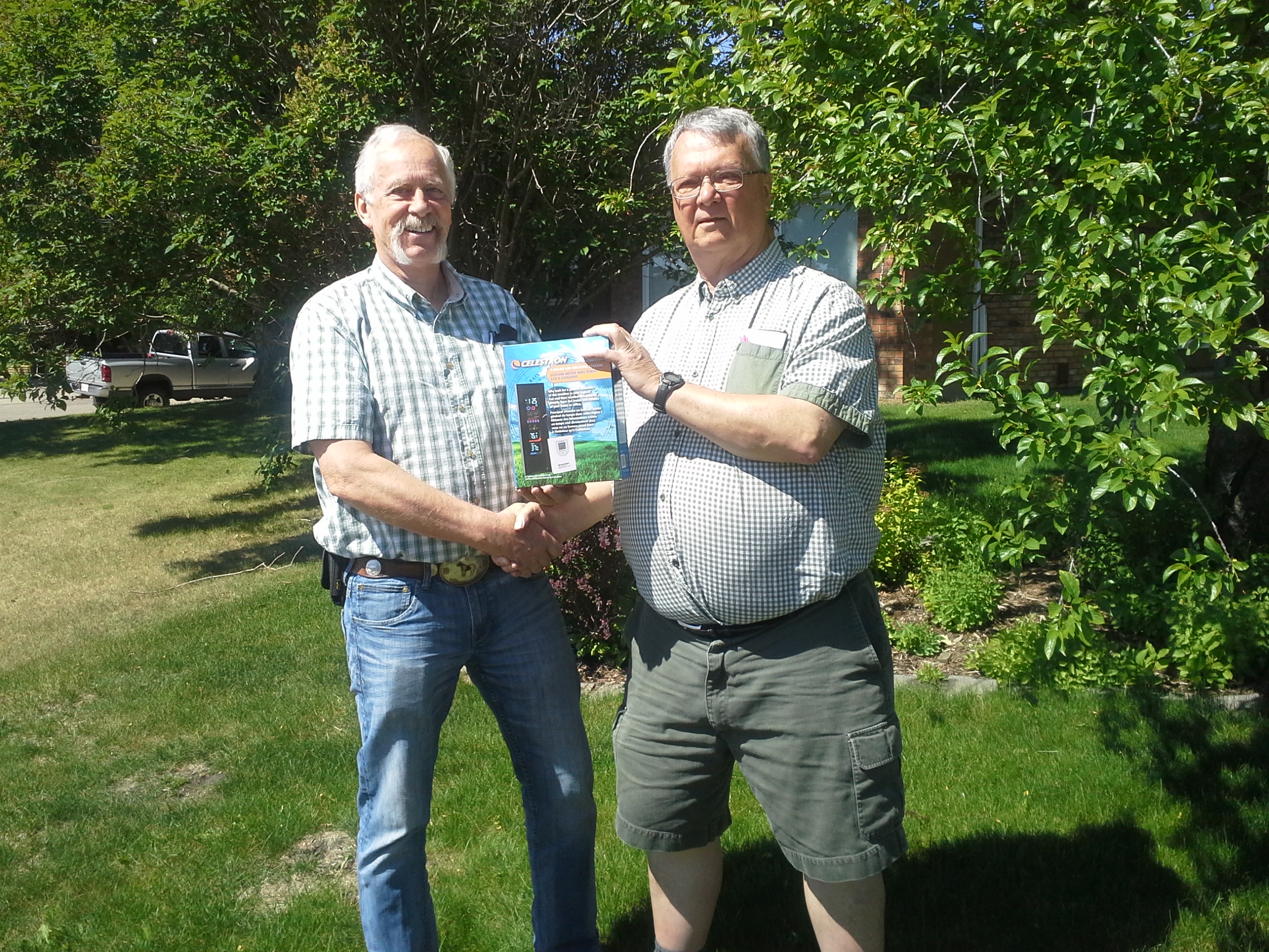
![20160620_113408[1]](https://caarc.ca/wp-caarc/wp-content/uploads/2016/06/20160620_1134081-1-300x225.jpg) Pictured here (right) John VA6SJA receives from Garry VE6CIA the Yaesu FTM 3200DR and the Celestron weather station draw prizes donated by Radio World Central which he won from the main draw and the Canwarn training draw.
Pictured here (right) John VA6SJA receives from Garry VE6CIA the Yaesu FTM 3200DR and the Celestron weather station draw prizes donated by Radio World Central which he won from the main draw and the Canwarn training draw.
Other prize winners include: Eric VE6HFF winner of an FTM 3100R donated by CAARC, Darren VA6WNG winner of an FTM 3100R donated by VE6HPY and VE6CIA, Rick VE6RAK winner of a Sangean Weather Alert Radio donated by Radio World Central, Pericles VA6PTA winner of the Raspberry PI2 donated by KoHen, and many others too numerous to mention.
Some of the ladies: Sheila (xyl of VE6HFF), Linda (xyl of VE6DE) and Brenda (xyl of VE6BLL) won the 2 beautiful hooked wall art and knitted blanket created and donated by Sylvia VE6SYL.
Special thanks go out to Greg VA6GMC and Karen VE6LDY for the super tasty pig and all the hard work that comes with preparing, cooking and presenting the wonderful pork that was on our plates. Also thanks to all the other donors of the wonderful food at the pot luck.
Chalk up another successful Ham Radio Pignic thanks to all of you that participated and made it all worth while.
First prize, $500- Brad Kolody VA6BMK from Rocky Mtn House
Second prize, $200- Brian Davies VA6BD from Innisfail
Thank you everyone who purchased tickets to support the repeater system. See you next year!


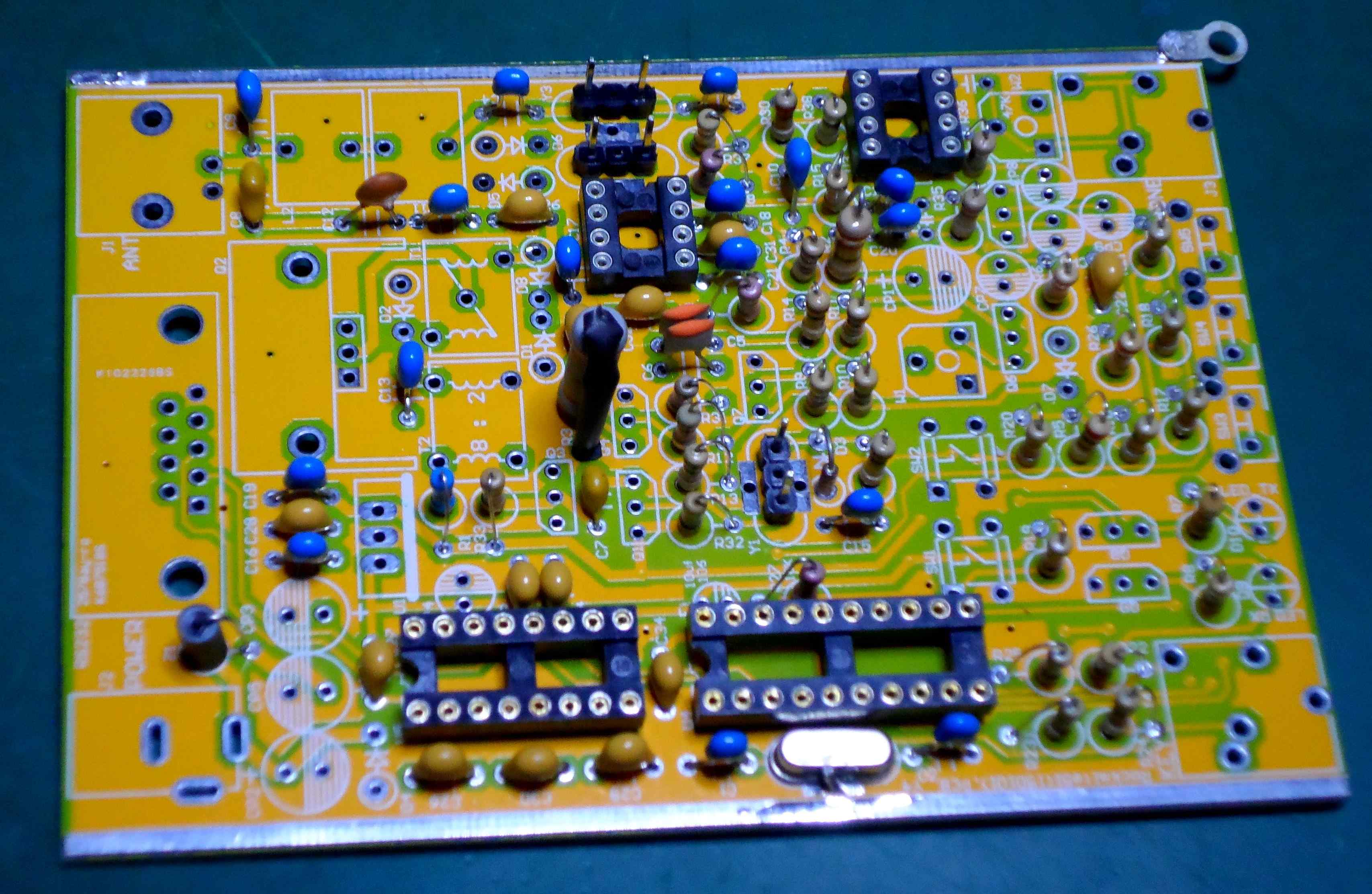
Super Rock Mite 40m CW QRP XCVR
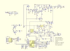
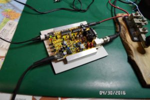
I bought this kit for US$16 including postage.  It features a keyer and substantial output power (see below).  I am posting some of the documentation inconsistencies that I found – hopefully this will smooth the build for others.  I bought my kit here   http://www.banggood.com/DIY-51-Super-Rock-Mite-RM-Kit-CW-Transceiver-Shortwave-Telegraph-p-991246.html
caveat emptor
Clarification to Bill of Materials (list of components)
- C22 to C34 0.1 uF (104) disc capacitors. Approximately half of these capacitors tested within 20% of designated value, the rest within 50% of designated value. One capacitor was 0.028 uF. All these capacitors were replaced with quality ceramic components testing within 10% or better of designated value.
- C25 and C26: these are apparently the same capacitor. Documentation inconsistency between versions?
- C13 to C21: 0.01 uF (103) disc capacitors. Less than half were within 20% so I replaced them all with good ceramic capacitors.
- C35: 470 pF is necessary to prevent oscillation in the NE5532. Put it in.
- Install the 100 pF capacitor located on the edge of the board between W2 and U3.
- Y1, Y2, Y3: I used DIP header pins on the board and soldered the crystals to DIP sockets. Cut strips of 3 pins each and remove the center pin for the header on the board. This arrangement will permit you to QSY to 7.030 / 7.040 when you find some appropriate crystals. I found 7.0375 crystals in the same holder at US$0.10 each from Tayda Electronics and they should arrive in the mail any day now. The pins will also let you painlessly try the VFO/DDS mod as per the March 2016 QST article pp 39-44.

- R2, R3: The schematic states that 1 W resistors should be used however 1/4W resistors are supplied. R3 is in series with the emitter lead of the 8050 driver transistor. I looked up the specs on this transistor and it can handle sufficient current to fry a ¼ W resistor. I didn’t have a 1 W 22 ohm resistor in my parts so I used a 2W resistor. It protrudes a bit but fits. DO NOT use a wire wound resistor for R3 . I check inductance of the resistor before using it. For R2 I found a 1/2W 22 ohm resistor to substitute but I am not convinced it is necessary.
- Electrolytic capacitors: The BoM shows 16V electrolytics. My kit supplied 25V capacitors. I strongly recommend that you do not use 16V units with a 12V (13.6V) supply.
- D3: I have used the 1N4001 as a varicap however I also once wasted several hours troubleshooting because a 1N4001 diode somehow prevented crystal oscillation. I found that a BB221 varicap works well so that is what I used.
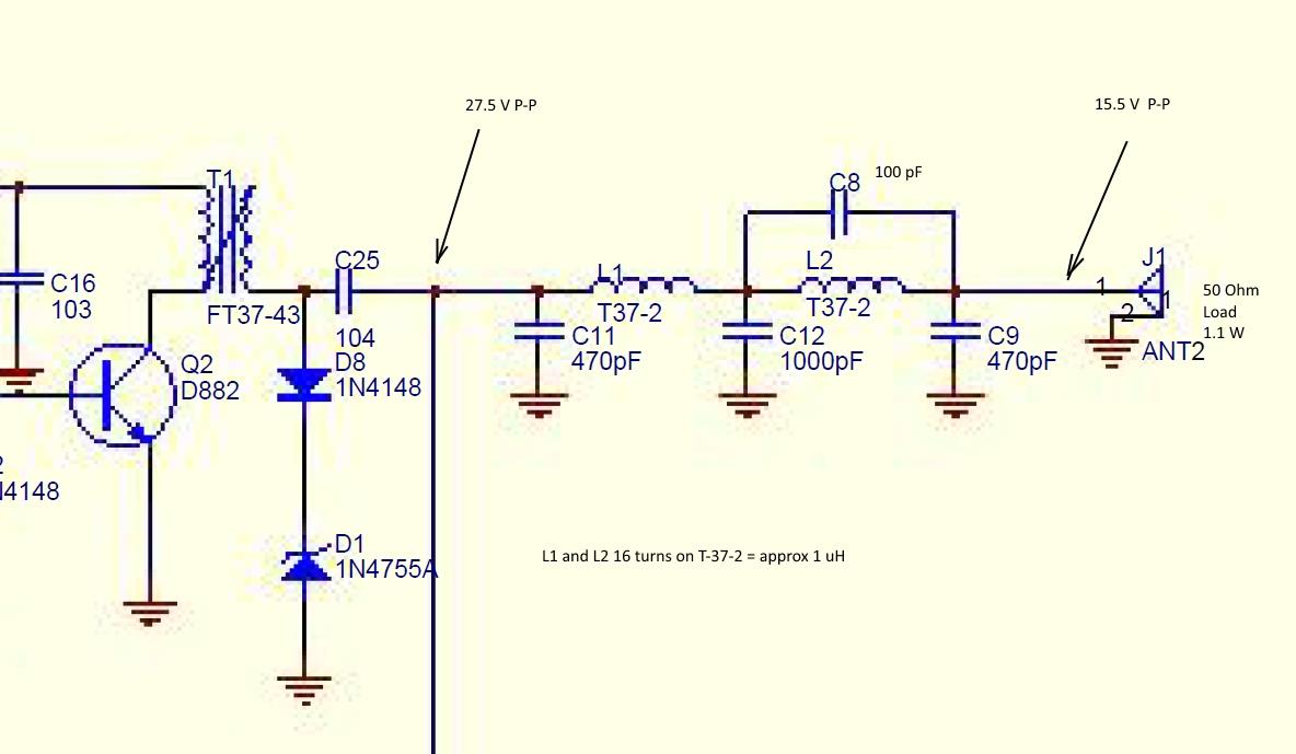
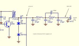
- L1 and L2: My toroid calculator gives a value of 1 uH for 16 turns on a T37-2 form. The photo in the Engrish instructions shows 17 turns. The LPF is not working well for me as I am seeing a drop of about 12 V P-P between the input and output sides of the filter section. I used tested capacitors, within 2% of given value,  in the filter. If anyone knows how to calculate the optimum values for L1, L2 please send me an email (QRZ.com).Â
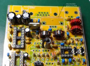
- Q2 output transistor. I cut a mica power transistor insulator to fit under the heat sink and superglued it in place. The solder resist under the heat sink is a good insulator but …
- LEDs: the long lead goes into the square pad. I used the green LED for receive and the red LED for transmit.
- For the initial smoke test, after connecting a dummy load to the antenna terminals, I put a 10 ohm 5W resistor in series with the supply. Current draw through the 10 ohm resistor was 85 mA.
- I am getting 1.1 watts out into a calibrated watt meter using a 12 V battery as a supply. As mentioned above, there is definitely a problem with my LPF. Once I get the LPF issue sorted out and up the supply voltage from my 13.6V buss, I expect to see several watts RMS out.
- I used a USB to RS232 cable to connect the Rock Mite to my computer after finding the English version of the software. The software definitely does something but needs further research. Who designs a board with an RS232 interface in 2016? I was lucky my patch cable worked.
On the air:  I received reports of clean keying from several hams within 100Km. A CQ in the evening brought a prompt response from Europe. The QSK works fine.  My straight key was recognized after sending a few V’s.  The side tone leaves room for improvement. I connected the audio out through a small digital audio amplifier module. I am confident that a good CW operator could fill his logbook using this transceiver. For the rest of us I suggest working stations within a few hundred Km during daylight hours – the large number of stations heard concurrently after dark overwhelm my ability to sort out signals by tone.
The PCB layout shows some thought and some nice features. It was designed without mounting holes made to slide into a ready-made case. As may be seen on the photos I had a groove machined into some aluminum bar stock to hold the PCB.
This kit fails its “ISO9002 audit” because of the “instructions†and the poor quality of the disc capacitors supplied. Google does a terrible job translating Mandarin to English.

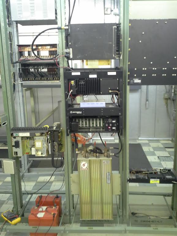 The new MSR2000 for VE6UK at Big Valley is now on 145.43MHz and still full time linked to VE6QE.


![20160620_113423[1]](https://caarc.ca/wp-caarc/wp-content/uploads/2016/06/20160620_1134231.jpg)
![20160620_113408[1]](https://caarc.ca/wp-caarc/wp-content/uploads/2016/06/20160620_1134081-1.jpg)